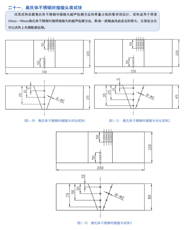
This kind of test block is designed according to the requirements of ultrasonic testing method and quality classification of austenitic stainless steel butt joint. The test block is suitable for ultrasonic testing method of austenitic stainless steel butt welding joint with thickness of 10mm ~ 80mm. The distance-amplitude curve is drawn by the measured data of the selected probe and instrument combination on the comparison block.

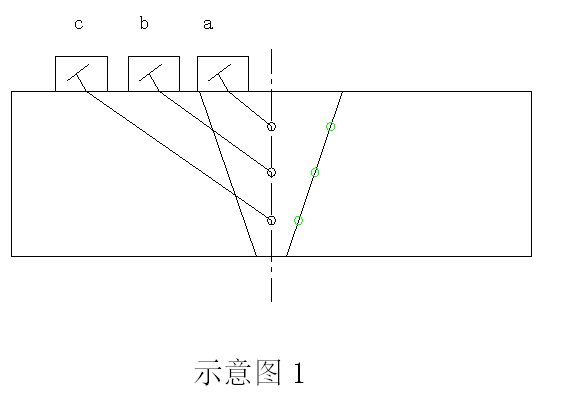
Test method: (1) When testing on both sides of the weld, make DAC curve with the transverse hole in the center of the weld to determine the detection sensitivity and evaluation. Select a verified oblique probe and place it at position A in Diagram 1. Move the probe back and forth so that the direct sound beam can get the maximum reflection echo on the φ2mm cross through hole. Adjust the echo amplitude to 80% of the height of the full screen, record the dB value at this time, which is the first point. The probe is placed at position b in Diagram 1, and the probe is moved back and forth to maximize the reflected echo of the direct sound beam on the φ2mm transverse through-hole. Adjust the echo amplitude to 80% of the height of the full screen, record the dB value at this time, which is the second point. The probe is placed at position c in Diagram 1, and the probe is moved back and forth so that the direct sound beam can get the maximum reflected echo on the φ2mm transverse through-hole. Adjust the echo amplitude to 80% of the height of the full screen, record the dB value at this time, which is the third point. And so on. Connecting the above points into a curve is the base line specified in the standard.

(2) When detecting only on one side of the weld, the sound beam should pass through the weld metal to make a DAC curve using the cross hole in the fusion zone. Select the verified oblique probe and place it at position a in Diagram 2. Move the probe back and forth so that the direct sound beam can get the maximum reflection echo on the φ2mm cross through hole. Adjust the echo amplitude to 80% of the height of the full screen, record the dB value at this time, which is the first point. The probe is placed at position b in FIG. 2, and the probe is moved forward and backward so that the direct sound beam can get the maximum reflected echo on the φ2mm transverse through-hole. Adjust the echo amplitude to 80% of the height of the full screen, record the dB value at this time, which is the second point. The probe is placed at position c in FIG. 2, and the probe is moved forward and backward so that the direct sound beam can get the maximum reflected echo on the φ2mm transverse through-hole. Adjust the echo amplitude to 80% of the height of the full screen, record the dB value at this time, which is the third point. The probe is placed at position d in FIG. 2, and the probe is moved forward and backward so that the direct sound beam can get the maximum reflected echo on the φ2mm transverse through-hole. Adjust the echo amplitude to 80% of the height of the full screen, record the dB value at this time, which is the fourth point. Connecting the above points into a curve is the base line specified in the standard.


